



Sorry, no sales person is available right now to take your call. Pls leave a message and we will reply to you via email as soon as possible.
Home/ PCB News/ Common Structures and Process Flow of Rigid-Flex PCBs
Common Structures and Process Flow of Rigid-Flex PCBs
2026-08-11
Rigid-flex printed circuit boards (R-FPCBs) are hybrid printed circuit boards formed by laminating flexible printed circuit boards (FPCBs) and rigid printed circuit boards (PCBs) through processes such as lamination, drilling, plating, and bonding. They combine the flexibility of FPCBs with the rigidity of PCBs, enabling bending or folding in specific areas while providing stable mechanical support and mounting platforms in other regions. This effectively saves internal space, reduces overall device size, and enhances electrical connection reliability. Consequently, R-FPCBs are widely used in aerospace, medical devices, wearable electronics, and high-end consumer electronics—fields that demand special considerations for space and performance. The core design concept involves stacking one or more rigid layers onto a flexible substrate, with electrical connectivity between circuits on the rigid layers and traces on the flexible layers achieved through plated through-holes, lamination interconnects, and other techniques. This approach facilitates component assembly, soldering, and debugging while ensuring installation flexibility and structural integrity.
Advantages and Disadvantages of Rigid-Flex Boards
Advantages
Combining the flexibility of FPCs with the rigid support of PCBs, they meet three-dimensional assembly requirements, significantly reducing the need for connectors and wiring harnesses, thereby lowering overall weight and volume.
Eliminating inter-board connectors reduces signal transmission loss and risks of poor contact, improving signal integrity for high-frequency/high-speed signals.
The transition zones between rigid and flexible sections allow dynamic bending or static folding, offering greater design freedom and facilitating thinner, more compact designs.
Disadvantages
The manufacturing process is complex, involving multiple lamination cycles, precision drilling, plating, coverlay lamination, and other steps, demanding stringent equipment capabilities and process controls.
Yield rates are relatively low, resulting in higher material waste and labor costs, leading to expensive unit prices and longer lead times compared to standard PCBs or FPCBs.
Repair is difficult; if internal traces or interlayer bonding fail, repair costs are extremely high.
Common Structural Types
Based on how flexible and rigid layers are combined, rigid-flex boards are primarily categorized into two typical structures:
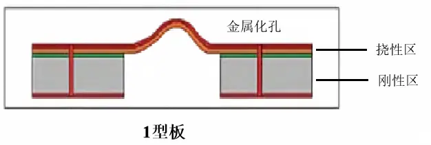
1) Single Flexible Layer + Multiple Rigid Boards (Type I)
In this structure, a single flexible substrate acts as the overall "skeleton," with multiple independent rigid boards laminated onto areas requiring mechanical support (typically at different localized positions on the flexible layer). The rigid regions are connected by exposed flexible segments, enabling bending or folding functionality. This configuration suits designs with dispersed rigid areas and longer flexible interconnect paths—for example, main and secondary board connections in foldable phones or multi-module sensor assemblies. Its key feature is simple rigid-flex transition design, though the flexible traces between rigid sections require special attention to bending fatigue resistance.
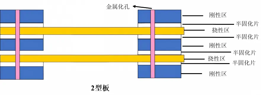
2) Multilayer Flexible + Multilayer Rigid Boards (Type II and Type III)
For more complex applications, the flexible layers can be designed as multilayer structures (including shielding layers or power/ground planes), while rigid regions may also adopt multilayer configurations. Electrical interconnections between layers are achieved through blind/buried vias or through-holes. Such structures are suitable for high-density interconnect (HDI) and high-speed signal transmission scenarios, such as phased-array radar transceiver modules or high-end medical ultrasound probes. Their advantage lies in extremely high integration density, but design and manufacturing complexity increase significantly, making interlayer alignment accuracy and lamination uniformity critical control factors.
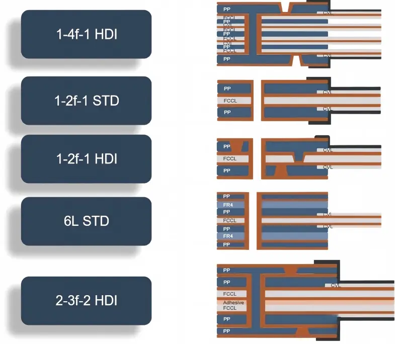
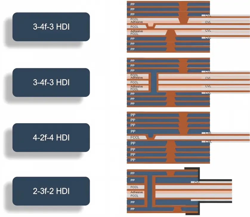
Derived structures are shown below
Manufacturing Process Flow
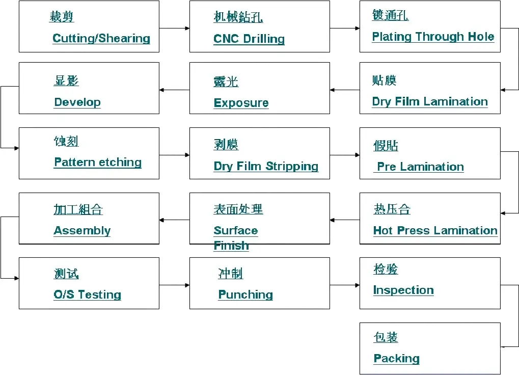

Simplified process flow for multilayer flexible boards
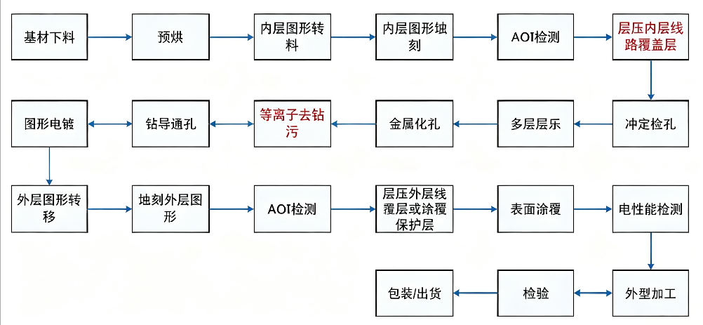
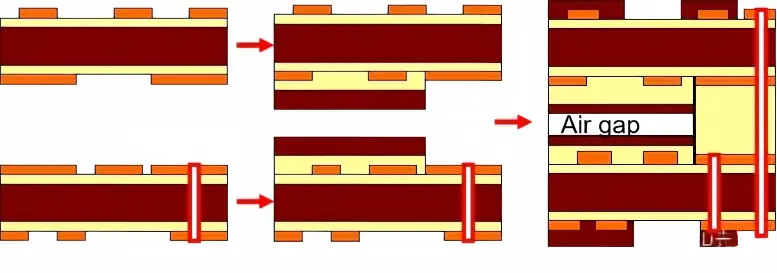
Four-layer flexible boards can have various structures: 2+2, 1+2+1, 1+1+1+1;
Similarly, five-layer and six-layer flexible board structures can be configured in multiple combinations using the above methods.
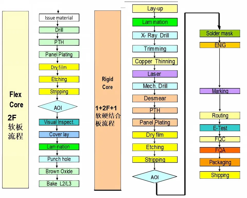
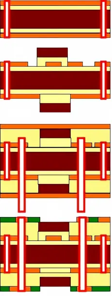
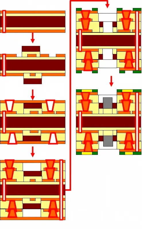
Rigid-flex board manufacturing process flow 2
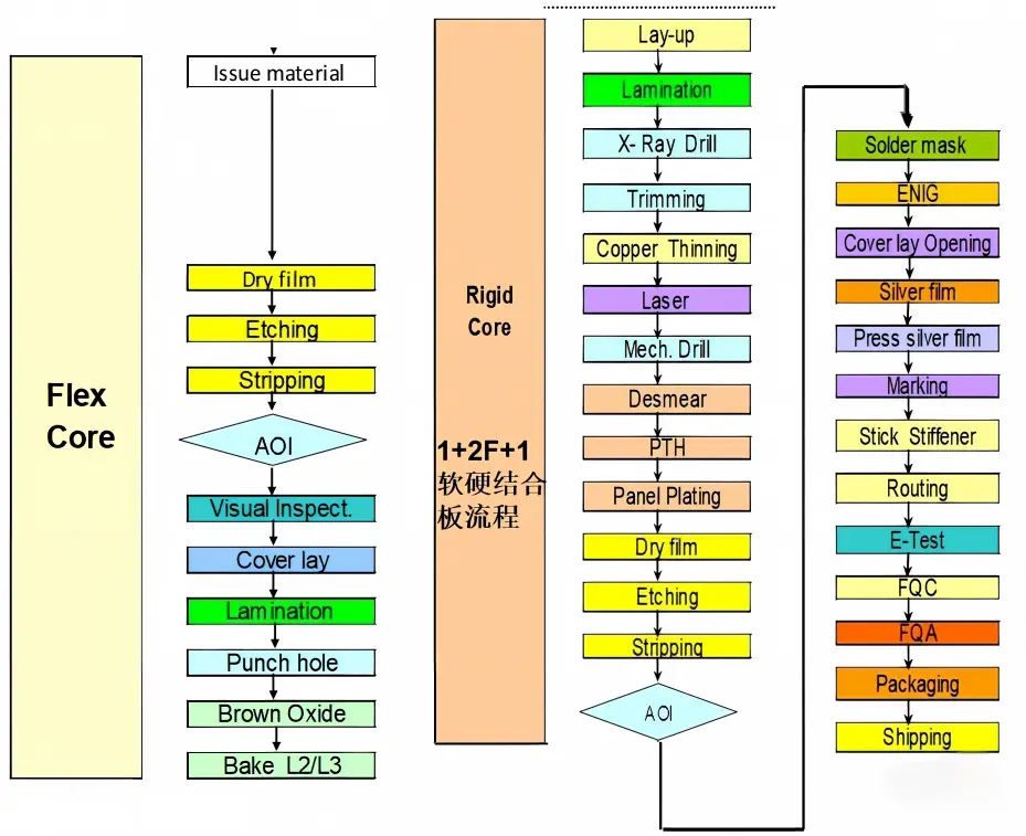
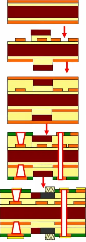
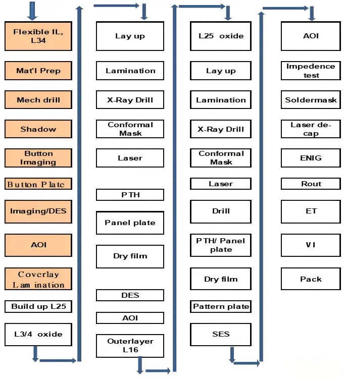
Rigid-flex board manufacturing process flow 3
trending news
Contact Us