



Sorry, no sales person is available right now to take your call. Pls leave a message and we will reply to you via email as soon as possible.
Home/ PCB News/ FPC-to-CCS Integrated Cover Plate for New Energy Battery Packs: Core Concepts, Mainstream Processes, and Technology Trends
FPC-to-CCS Integrated Cover Plate for New Energy Battery Packs: Core Concepts, Mainstream Processes, and Technology Trends
2026-08-03
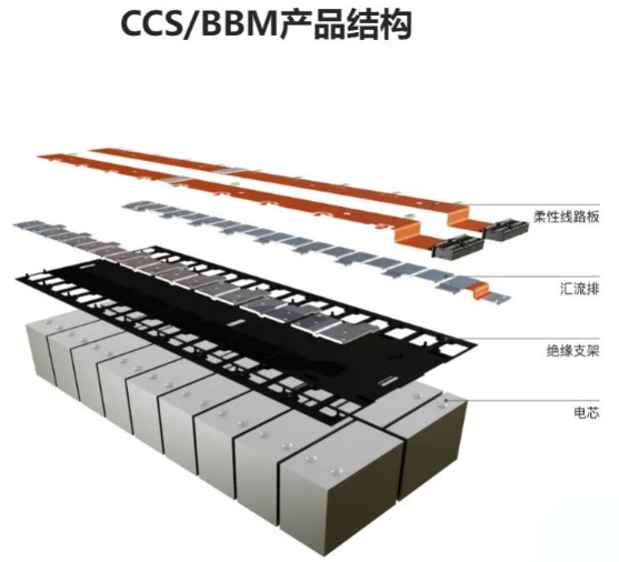
In the power battery pack of new energy vehicles, CCS (Cell Contact System) and FPC (Flexible Printed Circuit) are two core components, responsible for signal acquisition and power transmission respectively. For easier understanding, the battery pack can be analogized to the human body: FPC acts like the “sensory nerves” covering each cell, collecting voltage and temperature data in real time; while CCS is an integrated “functional module” combining sensory nerves, power transmission channels, and insulation protection. With clear division of labor and deep collaboration, they jointly form the underlying sensing and control network of the Battery Management System (BMS), providing fundamental assurance for the safe and stable operation of the battery pack.
I. Core Concept Analysis of CCS and FPC
(1) CCS Integrated Busbar (Cells Contact System)
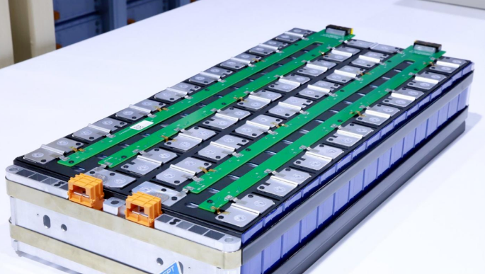
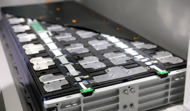
CCS (Cells Contact System), commonly known in the industry as an integrated busbar or battery cover assembly, is a highly integrated core functional component in power battery modules. It integrates multiple functions—including high-voltage electrical connections, cell signal acquisition, structural support and positioning, and electrical insulation—into one unit, fully replacing the traditional decentralized structure of “wiring harnesses + brackets.”
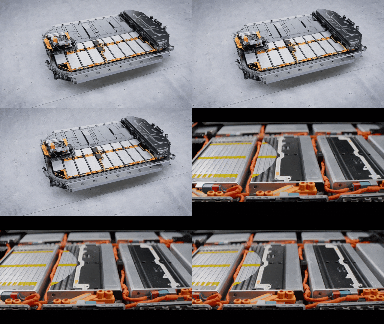
A standard CCS assembly consists of three core units:
Signal Acquisition Unit: Uses FPC as the core carrier to accurately collect and transmit cell voltage and temperature signals with minimal loss;
Plastic Structural Unit: Provides overall structural support, insulation isolation, and positioning fixation;
Conductive Current-Carrying Unit: Composed of copper or aluminum busbars (“copper/aluminum bars”), it carries high current and enables series/parallel interconnection among cells.
The core functions of CCS encompass three aspects:
① Constructing a high-voltage power circuit via metal conductive busbars to achieve series/parallel cell connections;
② Precisely acquiring voltage and temperature signals from each individual cell and uploading them to the BMS, providing data support for state estimation, balancing control, and overheat protection;
③ Some integrated CCS designs incorporate fuse protection structures, offering passive overcurrent and overheat protection to enhance system safety redundancy.
(2) FPC Flexible Circuit Board (Flexible Printed Circuit)
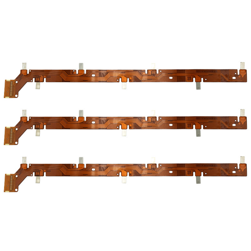
FPC (Flexible Printed Circuit) is fabricated using flexible substrates such as polyimide (PI) or polyester film (PET), through precision etching, surface-mounting, lamination, and other processes, giving it bendable characteristics. Within the CCS system, FPC serves as the core carrier for signal acquisition, integrating NTC temperature sensors and nickel collection tabs onto its circuitry to correspond precisely with individual cells, enabling high-accuracy, low-loss signal collection and transmission.
Standard FPC thickness ranges only from 0.1 to 0.3 mm, offering outstanding advantages such as ultra-thin lightweight design, arbitrary bendability, high circuit integration density, and neat wiring—making it highly compatible with the compact, high-integration trends in power battery packs.
The collaborative relationship among the three components can be concisely summarized as follows:
FPC — The “sensory nerve,” responsible for signal acquisition;
Copper/Aluminum Conductive Busbars — The “blood vessels” for power transmission, handling high-current flow;
Plastic Bracket — The “skeletal framework,” providing structural shaping and insulation protection.
Integrated into a single unit, these three elements form a functionally complete and structurally compact CCS assembly module.
II. Core Value of CCS in Power Battery Packs
Prior to 2022, domestic power battery packs commonly used traditional discrete copper wire harnesses for signal acquisition, following a “one wire per electrode” approach. As the number of cells surged, system integration increased, and signal accuracy requirements rose, this method revealed significant drawbacks: complex wiring occupying large space; heavy reliance on manual labor for assembly, limiting automation and production efficiency; numerous connection points increasing risks of poor contact and signal failure, making quality consistency difficult to ensure; and excessive weight hindering vehicle lightweighting.
The large-scale adoption of CCS integrated busbars has fundamentally transformed battery pack structural design and manufacturing processes. By consolidating dispersed signal harnesses, insulating brackets, conductive busbars, and components into a modular multi-in-one assembly, CCS delivers significant advantages:
Drastically reduces the number of parts, compresses structural thickness, and simplifies assembly procedures;
Enables compatibility with automated production lines, minimizing manual intervention and significantly improving production efficiency and product consistency;
Delivers exceptional lightweighting performance— a typical FPC-based CCS module can replace dozens of traditional wire harnesses, achieving several kilograms of weight reduction at the module level.
Currently, FPC-based CCS solutions have achieved a market penetration rate exceeding 60%, becoming the mainstream configuration for new energy passenger vehicle battery packs.
III. Mainstream CCS Manufacturing Processes and Key Characteristics
The industry employs a standardized two-dimensional classification for CCS technical solutions:by signal acquisition component type and by overall manufacturing process. Each solution exhibits distinct differences in structural form, physical performance, production cost, and application scenarios.
(1) Classification by Signal Acquisition Component
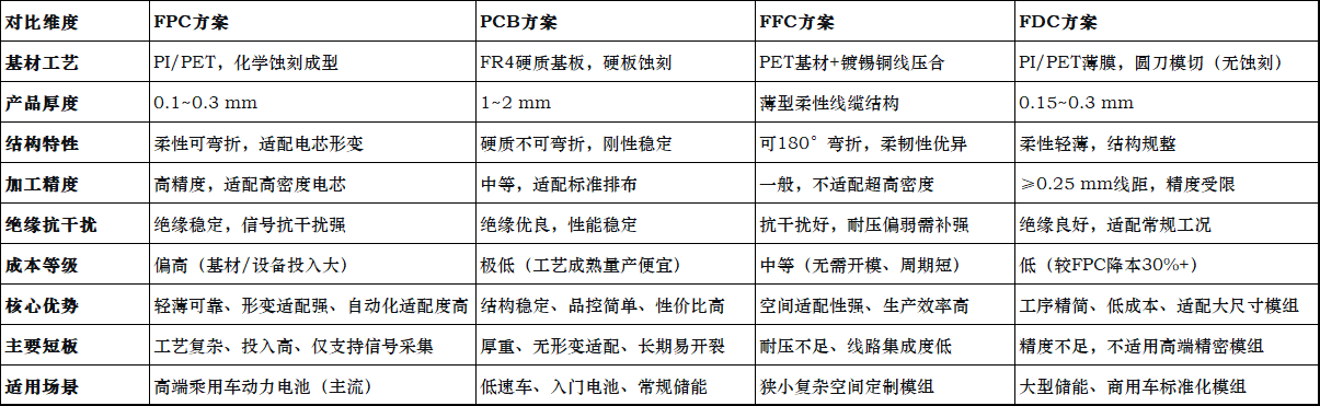
1. FPC Solution (Industry Mainstream)
Currently holding over 60% market share, the standard structure comprises: FPC flexible circuitry + nickel collection tabs + copper/aluminum busbars + thermoformed plastic sheet/PET film integrated via hot pressing.
Advantages: Ultra-thin and lightweight (substrate thickness only 0.1–0.3 mm), maximizing space utilization; circuits formed via integrated etching with minimal solder joints, ensuring excellent reliability and stability; flexible and bendable, capable of adapting to minor cell expansion/contraction during charge/discharge cycles; fully compatible with automated mass production with stable yield rates.
Disadvantages: High investment required for premium FPC materials and supporting equipment; complex processing technology; FPC handles only signal acquisition without high-current capability, necessitating use alongside metal busbars.
2. PCB Solution
Uses rigid FR4 epoxy resin substrate, with standard structure: rigid PCB board + nickel collection tabs + aluminum busbars + thermoformed plastic riveting/PET film hot pressing for fixation.
Advantages: Mature process, extremely low production cost, easy quality control; rigid substrate offers high flatness, dimensional stability, and resistance to deformation, suitable for standardized mass production.
Disadvantages: Substrate thickness reaches 1–2 mm, resulting in bulky structure and poor lightweighting performance; rigid and non-bendable, unable to accommodate cell expansion/contraction during cycling, leading to long-term stress cracking and signal acquisition anomalies, limiting application scope.
3. FFC Solution
Uses PET as insulating substrate, formed by laminating tinned copper wires with insulation layers—a simplified flexible signal transmission component.
Advantages: Excellent flexibility, capable of 180° folding, suitable for complex and confined assembly spaces; good electromagnetic interference resistance; no dedicated mold required, enabling high-efficiency automated lamination and short delivery cycles.
Disadvantages: Limited voltage withstand capability, requiring additional insulation reinforcement; lower circuit integration density, insufficient for high-density cell arrangements in premium modules.
4. FDC Solution
Uses PI/PET film as substrate, directly shaped via rotary die-cutting process, eliminating traditional etching—an economical alternative solution.
Advantages: Significant cost advantage—over 30% lower production cost than FPC solutions—ideal for large-sized, standardized high-volume modules.
Disadvantages: Limited processing precision, with minimum line width/spacing ≥0.25 mm, unable to meet high-precision acquisition needs for micro-pitch, high-density cells, unsuitable for high-end precision applications.
(2) Classification by Overall Manufacturing Process
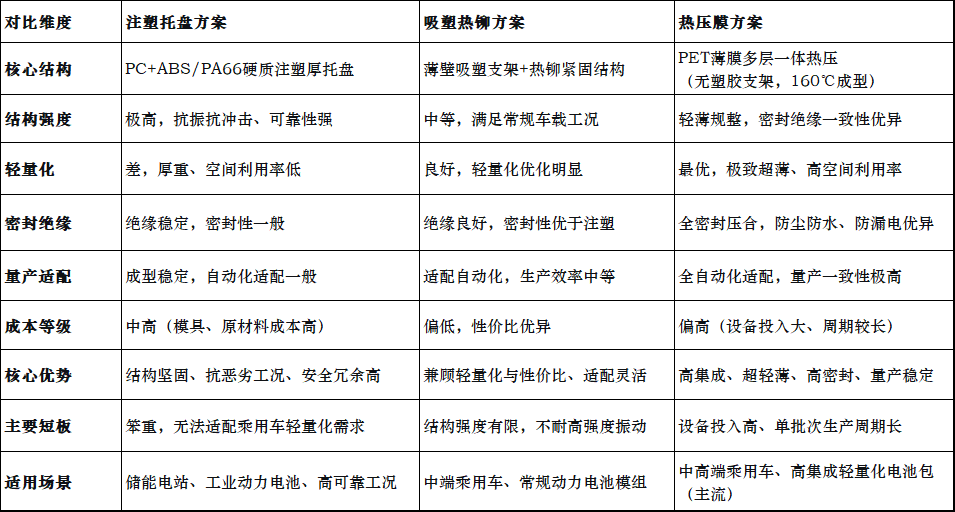
1. Injection-Molded Tray Solution
The earliest widely adopted industrial process, using flame-retardant engineering plastics such as PC+ABS or PA66, molded via high-temperature injection into a monolithic rigid tray as the structural skeleton, followed by mounting conductive busbars and acquisition components.
Advantages: High structural strength, excellent vibration and impact resistance, strong insulation reliability—suitable for stationary energy storage and large power battery applications with stringent safety requirements.
Disadvantages: Thick tray walls result in heavy and bulky assembly, poor lightweighting and space utilization, incompatible with thin-profile passenger vehicle demands.
2. Thermoformed Riveting Solution
A lightweight evolution of injection molding, replacing thick injection-molded trays with thin-wall thermoformed brackets, then securing FPC/PCB acquisition components and busbars via high-temperature thermal riveting.
Advantages: Significantly reduced wall thickness enables lightweighting and slim profile; lower material and production costs than injection molding, offering high cost-effectiveness; flexible structural adaptability compatible with various cell module specifications.
Disadvantages: Thin-wall structure offers lower mechanical strength than injection-molded trays, with somewhat reduced vibration and impact resistance, unsuitable for extremely rugged operating conditions.
3. Hot-Press Lamination Solution
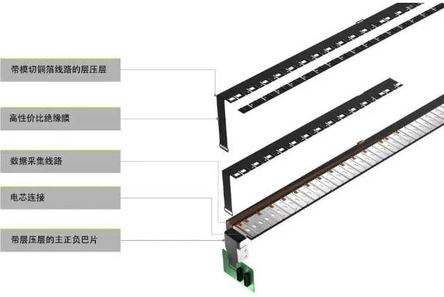
The fastest-evolving and most passenger-vehicle-compatible advanced process in recent years. Eliminates solid plastic brackets entirely, using high-strength PET insulating film as the carrier. Signal acquisition components, busbars, and insulating films are precisely stacked and aligned, then bonded into an ultra-thin integrated CCS assembly via single-step hot pressing at approximately 160°C under constant temperature and pressure.
Advantages: Extremely thin and lightweight structure with industry-leading integration density, maximizing internal battery pack space; fully sealed lamination ensures excellent dustproof, waterproof, and leakage-proof performance; high standardization enables full compatibility with automated mass production, delivering exceptional product consistency.
Disadvantages: High investment required for specialized hot-press equipment; longer curing cycle per batch results in higher overall production costs compared to injection molding and thermoforming.
IV. Comparison Summary of Mainstream CCS Process Parameters
(1) Comparison by Signal Acquisition Component Process
(2) Comparison by Overall Manufacturing Process
V. Technology Evolution Summary and Industry Development Trends
Reviewing the technological evolution path of CCS integrated cover plates, the industry has consistently iterated around five key directions: lightweighting, high integration, high reliability, automated mass production, and cost reduction. The technology roadmap has clearly progressed from traditional discrete wire harnesses → injection-molded bracket CCS → lightweight thermoformed rivet CCS → mainstream FPC + hot-press lamination integrated CCS.
Currently, the FPC flexible acquisition + PET hot-press lamination combination has become the optimal mainstream solution for passenger vehicle battery packs, thanks to its ultra-thin profile, high reliability, superior space utilization, and excellent mass production consistency. Meanwhile, emerging acquisition solutions like FFC and FDC are gradually gaining traction in energy storage batteries, commercial vehicle power batteries, and standardized modules, leveraging their differentiated cost advantages and forming a multi-technology competitive landscape.
For professionals involved in battery pack design, R&D, and manufacturing, precisely understanding the performance trade-offs, cost differences, and application-specific suitability of various CCS processes is crucial for effectively balancing safety, performance, and cost during product development—and serves as a vital foundation for optimizing battery system architecture and enhancing product market competitiveness.
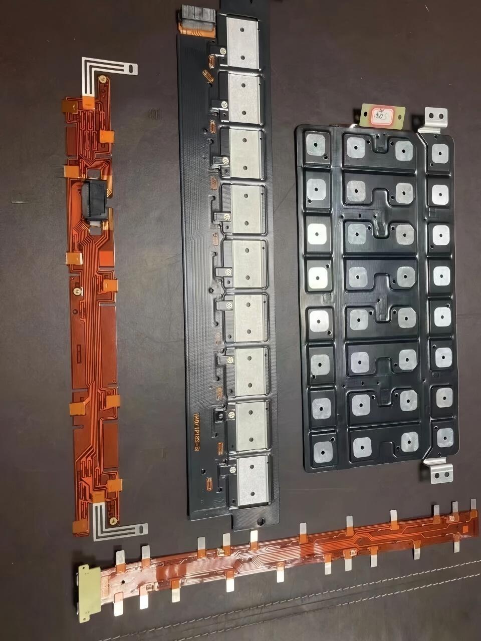
BYBON New Energy Battery Pack CSS Products
trending news
Contact Us