



Sorry, no sales person is available right now to take your call. Pls leave a message and we will reply to you via email as soon as possible.
Home/ PCB News/ Professional Selection Guide for Rigid PCBs, Flexible FPCs, and Rigid-Flex Boards
Professional Selection Guide for Rigid PCBs, Flexible FPCs, and Rigid-Flex Boards
2026-06-24
The selection of rigid PCBs, flexible FPCs, and rigid-flex boards directly determines a product’s structural form, electrical performance, reliability, and mass production yield. The industry commonly falls into two major selection pitfalls: exclusively choosing rigid boards to cut costs, which prevents implementation in irregular shapes or confined spaces; and blindly reusing FPCs to enhance integration, leading to cost redundancy, mismatched operating conditions, and increased quality risks.
None of the three board types is inherently superior—selection must strictly follow the principles of scenario compatibility, quantified parameter matching, operational condition compliance, and controllable cost. Based on IPC standards, SI/PI integrity, thermal simulation, and DFM-driven mass production risk control systems, this article upgrades empirical selection into a reviewable, quantifiable, and implementable standardized engineering solution, proactively preventing design rework, process failures, and reliability issues in mass production.
1. Rigid PCBs: Preferred for Fixed, High-Power Applications
Rigid PCBs primarily use FR4 substrates, offering mature processes, structural stability, and excellent thermal and electrical performance. They serve as the baseline solution for applications requiring no bending, high heat dissipation, and continuous long-term operation, delivering outstanding mass production tolerance and cost-effectiveness.
Substrate Grades and Operational Condition Matching (Quantified Standards)
Selection is based on Tg (glass transition temperature) ratings to match different industry loads and thermal conditions:
Standard FR4 (Tg 130–140°C): suitable for consumer electronics and home appliances under normal-temperature, low-load conditions;
Medium-Tg FR4 (Tg ≥150°C): suitable for general industrial control and medium/low-power intermittent-duty equipment;
High-Tg FR4 (Tg ≥170°C): suitable for 24/7 industrial operation and automotive applications in high-temperature, high-humidity environments, offering resistance to thermal delamination and multiple reflow cycles;
High-frequency specialty laminates: feature low Dk and low Df, ideal for RF, high-speed differential, and high-frequency communication circuits, effectively controlling impedance variation, signal loss, and crosstalk.
Core Performance Quantification Metrics
Mechanical Performance: strong rigidity with no deformation, capable of directly mounting light to heavy components without reinforcement;
Electrical/Thermal Thresholds: suitable for high-power, high-heat scenarios with continuous current ≥3A per circuit, local power dissipation ≥5W, long-term operating temperature ≤125°C, and local temperature rise ≥85°C; complete ground planes and copper pours ensure stable PI performance and minimal voltage drop;
Signal Performance: stable dielectric properties and controllable impedance support mid-to-high-speed transmission, making it the preferred substrate for high-speed and RF critical circuits.
Mass Production Advantages and DFM Design Red Lines
Mass production advantages: standardized processes, short prototyping lead times, high batch yields, and strong error tolerance—ideal for scalable production of double-sided, multilayer, and high-frequency boards.
Mandatory Risk Control Rules:
① No bending capability—any deformation directly causes delamination or trace breaks; pure rigid boards are prohibited in bent or irregular structures;
② High-power circuits must include complete ground planes and thermal copper pours to prevent localized overheating and premature component failure;
③ Industrial, automotive, and high-temperature applications mandatorily require high-Tg (≥170°C) materials—standard FR4 mixing is prohibited.
Applicable Scenarios and Typical Cases
Ideal for fixed-structure, non-deforming devices requiring high heat dissipation, high reliability, and strict mass production cost control. Typical applications: high-power power supply boards, industrial PLCs, variable frequency drive boards, appliance main controllers, server/router motherboards, fixed automotive ECUs, and medical fixed power boards—all capable of stable, continuous mass production.
2. FPC Flexible Boards: Specialized Solution for Irregular, Confined Spaces with Dynamic Bending
FPCs use PI/PET flexible substrates, offering thinness, 3D routing, curved-surface conformity, and repeated bendability—ideal for tight, irregular spaces and dynamic hinge mechanisms. However, their thermal and electrical performance has clear limits; over-specification must be avoided.
Substrate Selection Breakdown
PET substrate: low-cost option for static bonding, low-frequency bending, and short-lifetime consumer applications;
PI substrate: high-temperature resistant, fatigue-resistant, and electrically stable—the mainstream choice for high-frequency dynamic bending and long-lifetime premium devices.
Quantified Operating Conditions and Bend Life Standards
Electrical Limitations: only suitable for ≤2A per circuit, ≤3W local power dissipation, and ambient-temperature cooling; exceeding these causes copper heating, substrate carbonization, and trace fractures;
Bend Life Classification:
① Standard FPC: 10,000–30,000 cycles—suitable for low-frequency appliance hinges;
② High-durability gold-plated FPC: 50,000–100,000 cycles—for wearables, foldables, gimbals, and other high-frequency dynamic structures.
2.3 Performance Limitations and Operational Constraints (SI/PI/Thermal Simulation)
① Extremely poor heat dissipation—FPCs prohibited in areas with temperature rise >85°C;
② Poor high-frequency signal stability and high loss—strictly forbidden in high-speed differential or RF core circuits;
③ Inadequate PI performance—large currents cause abnormal voltage drops and power rail jitter, unsuitable for high-power applications;
④ No self-supporting capability—cannot independently mount SMT components or connectors.
Mandatory FPC DFM Mass Production Guidelines
① Heavy components like ICs and connectors must use steel or PI stiffeners—bare-board mounting is prohibited to prevent pad tearing and solder misalignment;
② Pure bending zones must not contain vias, pads, or components to avoid stress-induced breaks or delamination;
③ Trace width and spacing in dynamic bend zones must be 1.5× standard to reduce fatigue fracture risk;
④ Avoid large copper pours on flex areas to prevent thermal deformation from pulling traces.
Applicable Scenarios and Typical Cases
Used in compact, irregular, curved, or repeatedly opening/closing applications where thinness and high integration are prioritized—replacing discrete wiring harnesses to improve assembly efficiency. Typical applications: wearable hinge flex circuits, TWS earphone internal wiring, smartphone display/fingerprint flex cables, laptop hinges, camera flip flexes, drone gimbals, endoscope probes, and industrial micro-motion interconnects.
3. Rigid-Flex Boards: Optimal Integrated Solution for High-End Hybrid Structures
Rigid-flex boards integrate FR4 rigid zones with PI/PET flexible zones, combining the high-power stability of rigid boards with the dynamic bending capability of FPCs—specifically designed for hybrid architectures with “fixed component zones + movable interconnect zones,” ideal for premium, highly integrated precision devices.
Quantified Zonal Performance
Rigid zones: match high-Tg rigid board performance—supporting high power, high current, high heat dissipation, and high-speed signals;
Flex zones: strictly adhere to FPC operational thresholds—only suitable for low/medium current and ambient-temperature dynamic interconnects.
Specialized DFM Risk Control Points
① Rigid-flex transition zones are structural weak points—require stress-relief design; prohibit right-angle traces and dense vias; minimum bend radius ≥0.8mm;
② Limit copper coverage in flex zones to prevent thermal-mechanical mismatch from tearing traces;
③ High design and process barriers—stack-up, thickness, bend tolerance, and lamination processes must be confirmed early to avoid batch structural defects.
Applicable Scenarios and Typical Cases
Suitable for premium devices with stringent requirements on form factor, integration, and reliability—and sufficient budget: foldable device interconnect boards, camera body-lens adapter boards, portable precision testers, minimally invasive medical control boards, smart lock hinge-integrated boards, and precision industrial inspection equipment.
Key Limitation: complex design, long process cycle, and highest mass production cost—not suitable for general low-cost volume projects.
4. Industry Reliability Compliance Tiers (Baseline for Precise Scenario-Based Selection)
Define selection baselines per industry standards to prevent under-specification or over-engineering:
Consumer Electronics: RoHS compliant, standard temp/humidity conditions—prioritize cost-optimal solutions;
Industrial Equipment: mandate high-Tg materials—resistant to humidity, aging, and vibration—supporting 24/7 operation;
Medical Devices: comply with ISO 13485—high insulation, low outgassing, high stability; prefer high-durability PI-FPC or rigid-flex for miniaturized flexible applications;
Automotive: mandate Tg ≥170°C materials—withstanding thermal shock and severe vibration; use rigid boards in fixed zones and high-durability FPCs in dynamic zones.
5. Three-Tier Engineering Selection Model
Replace empirical selection with a standardized, stepwise, hard-rejection process:
Tier 1 Rejection Criteria: bending/irregular shape required → reject pure rigid boards; high power/high temp/high-speed RF required → reject pure FPCs;
Tier 2 Matching Criteria: verify parameter alignment across temperature zones, current/power, signal speed, bend life, and compliance levels;
Tier 3 Cost & Mass Production Criteria: balance performance and cost based on production volume, lead time, and process tolerance to finalize the optimal solution.
6. Cross-Industry Scenario-Specific Application Summary
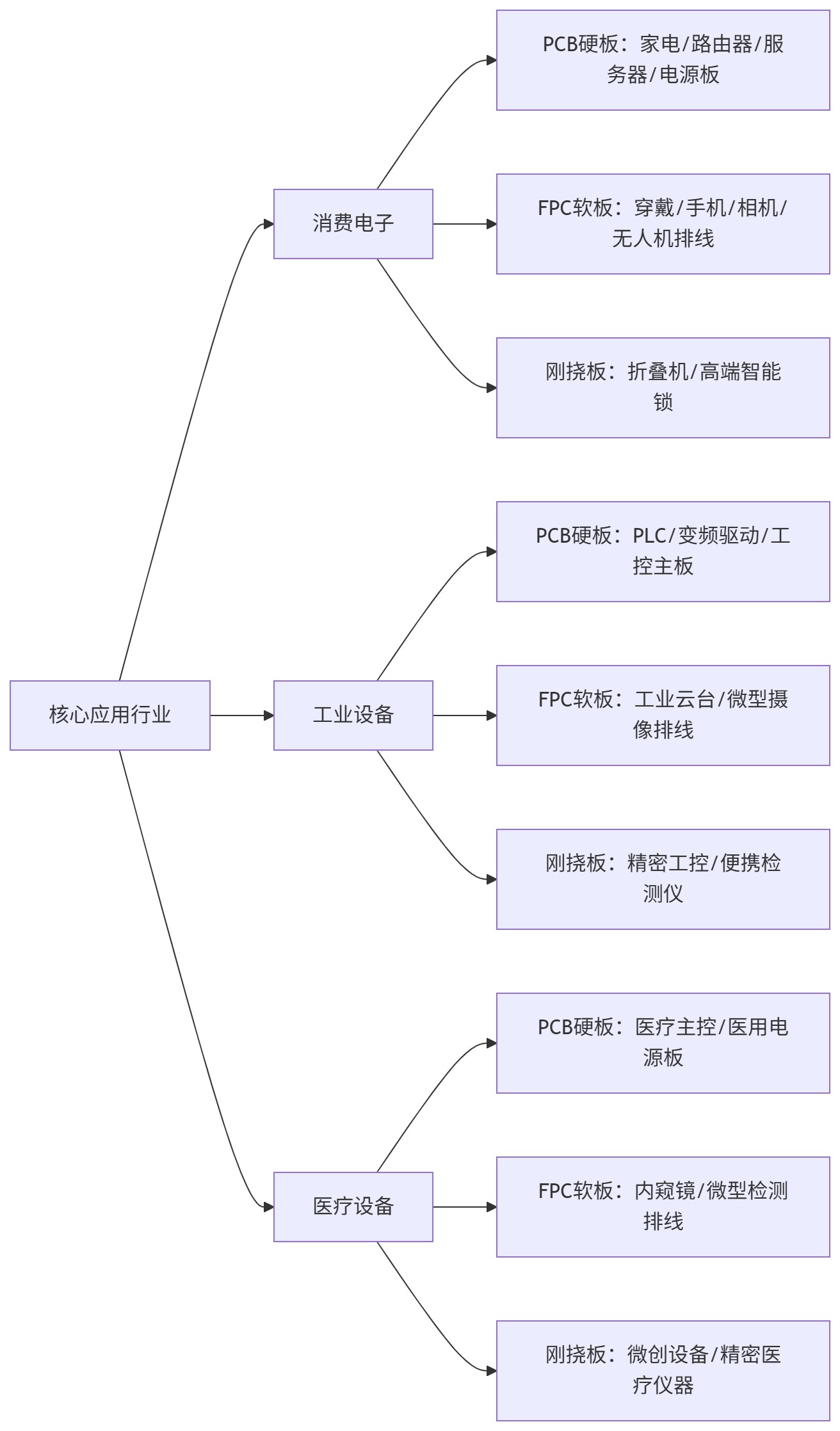
Consumer Electronics (Thin, Highly Integrated, Cost-Controlled Mass Production)
Rigid PCBs: routers, servers, appliance main controllers, high-power supplies, fixed automotive ECUs (fixed, heat-dissipating, non-bending scenarios);
FPCs: display/fingerprint flexes, foldables, wearables, TWS earphones, laptop hinges, gimbal flexes (tight, high-frequency bending scenarios);
Rigid-Flex Boards: foldable devices, premium smart locks, consumer-grade precision testers (fixed mounting + localized bending).
Industrial Equipment (High Stability, Long Life, EMI Resistance)
Rigid PCBs: PLCs, VFDs, industrial high-power supplies, industrial main controllers (high current, high heat, 24/7 operation);
FPCs: industrial micro-camera flexes, small gimbal hinges, confined-space interconnects (micro movable structures);
Rigid-Flex Boards: premium precision industrial controls, portable industrial testers (balancing stability and irregular assembly).
Medical Devices (High Precision, Miniaturization, High Reliability)
Rigid PCBs: medical main controllers, medical power drivers (fixed chassis power/thermal management);
FPCs: endoscope probes, small medical sensor bendable flexes (micro insertion, curved flexible fit);
Rigid-Flex Boards: minimally invasive medical control boards, premium precision testers (high-precision mounting + localized bending).
7. Full-Parameter Quantified Selection Reference Table
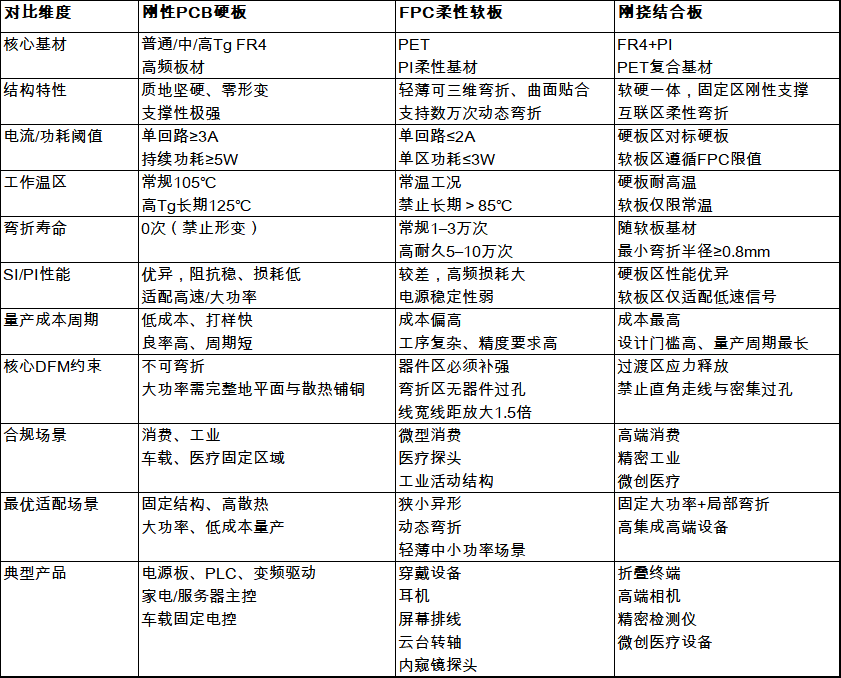
Board selection isn’t about hierarchy—it’s about parameter alignment, operational compliance, DFM control, and cost optimization. Rigid PCBs suit high-power, high-stability, cost-sensitive mass production; FPCs solve integration challenges in irregular, confined, dynamic-bending applications; rigid-flex boards meet the demands of premium devices requiring hybrid structural integration. Strict adherence to the three-tier selection model and quantified operational red lines prevents selection errors, design rework, and mass production risks—providing standardized technical support for product development finalization, process review, and scalable manufacturing.
trending news
Contact Us