



Sorry, no sales person is available right now to take your call. Pls leave a message and we will reply to you via email as soon as possible.
Home/ PCB News/ Stator-Coreless Axial Flux Motor: PCB Winding Structure, Key Design Considerations, and Application Prospects
Stator-Coreless Axial Flux Motor: PCB Winding Structure, Key Design Considerations, and Application Prospects
2026-05-26
Axial-flux permanent magnet (AFPM) motors can be categorized into two major technical systems based on stator structure: cored and coreless types, each suited for different operating conditions. Existing research has predominantly focused on magnetic circuit optimization and pole-slot matching design for cored AFPM motors, while systematic studies on coreless variants remain relatively scarce. This paper takes the printed circuit board (PCB) winding-based coreless AFPM motor—the fastest to achieve industrialization—as the research subject. It systematically analyzes the fundamental technical advantages of the coreless structure, classifies and investigates the adaptability of various PCB winding topologies, dissects key winding design parameters and manufacturing constraints, elucidates Halbach permanent magnet array-based magnetic circuit optimization strategies, summarizes current industrialization barriers, and forecasts technological evolution trends and market application prospects in light of the industry’s supply chain landscape.
The single-stator dual-rotor topology is the dominant configuration for coreless AFPM motors. This structure eliminates the traditional silicon steel stator core; instead, the winding assembly is directly mounted onto a non-magnetic insulating substrate. This fundamentally eradicates stator iron losses and hysteresis losses while effectively suppressing eddy current losses in the rotor permanent magnets, thereby comprehensively enhancing overall energy conversion efficiency. Moreover, the absence of cogging torque in coreless designs enables smooth torque output across all speeds and load conditions, significantly reducing torque ripple and operational vibration, and offering markedly superior dynamic response and running smoothness compared to conventional cored axial-flux motors.
I. Technical Breakthroughs and Process Innovations in Coreless Structures
Currently, stator windings for coreless AFPM motors primarily follow two technical routes: traditional wound coils and PCB-printed windings. These differ significantly in forming principles, processing precision, product consistency, and mass-production compatibility—factors that critically constrain motor performance and industrial scalability.
Traditional wound coils typically employ vacuum resin casting encapsulation, which suffers from notable process limitations: coil winding relies on manual positioning, resulting in poor dimensional control and frequent issues such as coil misalignment and warping of the winding disc. During high-speed operation, loose winding structures are prone to axial runout, exacerbating vibration and noise. As motor rated power increases, so do the number of turns and conductor volume, further amplifying these defects—leading to low yield rates, poor batch-to-batch consistency, and persistently high labor costs. Consequently, this approach struggles to meet the demands of large-scale industrial production.
In contrast, PCB printing technology—characterized by ultra-thin flat structures, high parameter precision, and standardized manufacturing processes—perfectly aligns with the design and production requirements of coreless AFPM motor stator windings. This method integrates copper foil conductors directly into an insulating substrate via etching, enabling precise control over coil dimensions, spacing, and layer count, thereby resolving inherent flaws of traditional wound coils at the process level. As a leading domestic provider of high-precision specialty PCBs for industrial applications, Baineng Yunban has specialized in manufacturing industrial-grade specialty circuit boards for over two decades, focusing on customized products such as high-power thick-copper boards, high-multilayer precision boards, and ceramic substrates. The company offers one-stop PCB winding solutions tailored for motors and, supported by automated production lines and comprehensive quality inspection systems, meets mass-production needs across various power ratings of coreless AFPM motors, establishing itself as the industry’s mainstream industrialization platform.
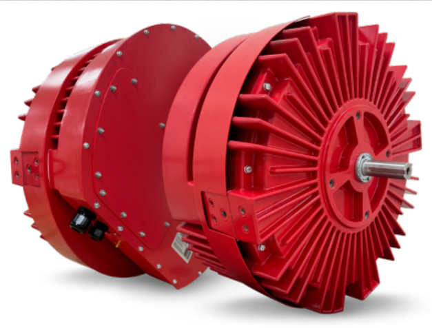
Based on electromagnetic design and engineering practice, PCB windings offer four revolutionary advantages over traditional wound coils:
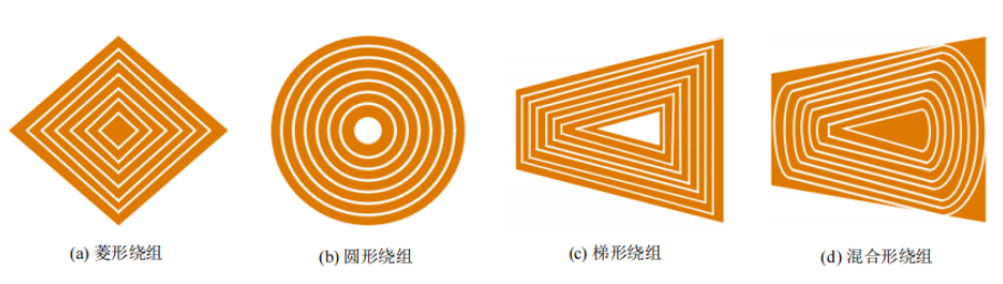
High Design Freedom: Coil topologies—including circular, trapezoidal, rhombic, and hybrid shapes—can be custom-etched based on electromagnetic simulation results. Iterative optimization of turn count and end-winding geometry can be achieved without reconfiguring production lines, accommodating applications ranging from low-power precision drives to medium- and high-power industrial transmissions.
Exceptional Consistency: Standardized PCB etching and lamination processes eliminate dimensional variations caused by manual winding. Key electromagnetic parameters—such as resistance, inductance, and flux linkage—can be controlled within ±1%, ensuring higher reliability and suitability for large-scale industrial manufacturing.
Superior Power Density: PCB winding thickness can be precisely controlled at the millimeter scale, effectively reducing the equivalent air gap length, minimizing redundant permanent magnet usage, and shrinking axial dimensions. This achieves both lightweighting and enhanced torque and power density.
Strong Mechanical Stability: The rigidity and flatness of the insulating substrate far exceed those of cast windings, completely eliminating axial movement or runout. Vibration and noise under high-speed operation are significantly reduced, greatly improving durability and stability during long-term fatigue operation.
II. PCB Stator Winding Topologies and Optimization Design
Based on conductor layout and excitation characteristics, PCB windings for axial-flux motors can be classified into non-overlapping concentrated windings and distributed windings. These topologies differ in magnetic coupling behavior, loss distribution, and output performance, requiring careful selection based on application scenarios, power ratings, and thermal management conditions—a critical aspect of multi-objective motor optimization.
(1) Non-Overlapping Concentrated Windings
Non-overlapping concentrated windings feature simple structures and low wiring complexity, serving as the foundational topology for low- to medium-power PCB-based coreless AFPM motors. Mainstream configurations include rhombic, circular, trapezoidal, and hybrid circular-trapezoidal forms, each with distinct performance trade-offs and application niches:
Rhombic Windings: Feature the shortest end-turn length, resulting in low DC copper losses and high operational efficiency. However, they suffer from limited flux linkage area and low copper utilization, restricting torque output—making them ideal for high-efficiency, light-load applications.
Circular Windings: Possess extremely simple end structures and the lowest additional losses among the four topologies. However, constrained by maximum effective turns, their magnetic coupling is weak, yielding insufficient back-EMF—suitable only for miniature, low-power precision drives.
Trapezoidal Windings: Offer high winding factors and large flux linkage, delivering optimal back-EMF and torque density—widely adopted in medium- and high-power industrial motors. Their drawback lies in excessively long end conductors, causing localized copper loss concentration and thermal hotspots that accelerate insulation aging and shorten stator lifespan. To address this industry challenge, Baineng Yunban has developed a thick-copper PCB solution using integrated 2oz inner/outer layer copper foil. Compared to standard 1oz copper cladding, this doubles current-carrying capacity and reduces local temperature rise by over 42%, resolving thermal accumulation at the process level and enhancing long-term reliability.
Hybrid Circular-Trapezoidal Windings: A composite optimized topology combining the low-loss advantage of circular windings with the high power density of trapezoidal ones. By replacing straight end segments with curved arcs, it improves flux linkage efficiency and torque output while dispersing thermal concentration zones—achieving the best overall balance of efficiency, power, and thermal performance among the four topologies.
(2) Distributed Windings
The core distinction between distributed and concentrated windings lies in conductor arrangement and conduction method: distributed windings use uniformly sized active conductors and leverage PCB metallized via technology to enable multi-parallel-path conduction, significantly boosting overall current capacity and reducing equivalent internal resistance and copper losses.
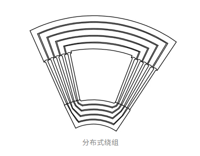
Distributed windings employ full-pitch coil integration, achieving substrate space utilization exceeding 85%. Under identical physical dimensions and permanent magnet configurations, they deliver significantly higher no-load back-EMF and winding utilization than concentrated windings, fully harnessing the magnetic potential of permanent magnets and balancing efficiency with power density—making them ideal for medium- to high-power continuous-operation applications such as data center cooling and large-scale industrial equipment.
III. Key Design Parameters and Process Constraints for PCB Stator Windings
PCB stator winding design must establish a three-dimensional constraint model encompassing electromagnetic performance, process feasibility, and production cost. Unlike consumer-grade PCBs, motor-specific PCB windings impose stringent industrial standards on parameters such as copper thickness, trace width/space, and layer count/board thickness. Leveraging extensive experience in high-power motor PCB manufacturing, Baineng Yunban has iteratively refined over 100 specialized processes, enabling customized implementation solutions that holistically balance electromagnetic performance and mass-production cost.
(1) Winding Copper Thickness
The industry commonly uses ounces (oz) to denote PCB copper thickness, with 1 oz = 0.035 mm. For commercial coreless AFPM motors, single-layer PCB windings typically use 3–4 oz copper. Copper thickness directly determines conductor cross-sectional area and is thus a fundamental parameter governing current capacity, copper loss distribution, and power rating. To meet high-current-density demands in high-power motors, Baineng Yunban offers gradient thick-copper customization from 2–6 oz. Its proprietary 16-layer high-power coil board features uniform 2oz thick copper on inner/outer layers, combined with specialized lamination processes to prevent delamination and misalignment—ensuring stable long-term current conduction under high-load conditions.
(2) Matching Relationship Among Trace Width, Spacing, and Copper Thickness
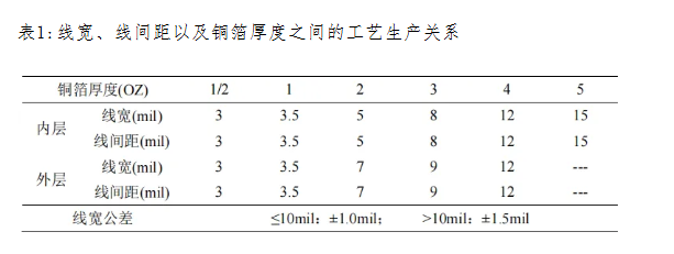
PCB winding trace width and spacing have fixed process thresholds strongly coupled with copper thickness and layer count: thicker copper and more layers increase etching difficulty, raising the minimum feasible trace width/spacing. Designs below these thresholds risk short circuits or open traces.
From a design perspective, wider traces are needed for high-current applications to reduce conduction resistance and suppress temperature rise, while narrower traces can be used in low-current precision applications to maximize substrate utilization. Thus, trace width and spacing must be optimized through iterative electromagnetic simulations, considering manufacturer capabilities, rated current, loss targets, and space efficiency. In the specialty PCB domain for motor windings, Baineng Yunban achieves minimum trace/space of 2.95/3.54 mil (0.075 mm) and supports differential copper thickness between inner and outer layers, simultaneously meeting high-frequency low-current control and high-power high-current drive requirements.
(3) PCB Layer Count and Board Thickness Constraints
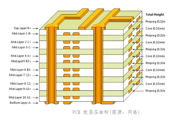
With fixed board thickness, increasing layer count expands total conductor cross-section and boosts power output—but faces dual constraints: process-wise, multi-layer lamination risks interlayer misalignment, dielectric damage, and board warpage, reducing yield as layer count rises; performance-wise, more layers thicken the stator substrate, lengthening the equivalent air gap, increasing leakage flux, and attenuating magnetic flux density—requiring additional permanent magnets to compensate, which inflates volume and cost, undermining competitiveness. Baineng Yunban precisely balances this trade-off, achieving up to 28-layer precision PCB integration. Its 12-layer three-stage HDI ultra-thin winding board enables efficient multi-layer interconnection within a 1.2 mm board thickness, perfectly resolving the core design conflict of “ultra-thin size with multi-layer windings” in axial-flux motors.
IV. Rotor Structure Innovation: Halbach Permanent Magnet Array Optimization
Due to the coreless structure, PCB-wound AFPM motors exhibit significantly larger equivalent air gaps than traditional cored motors, often suffering from low air-gap flux density and limited torque output. Industry optimization strategies fall into two categories: permanent magnet material upgrades and magnetic circuit optimization. Among these, the Halbach array stands out for its optimal balance of low cost, high flux density, and low harmonic distortion, making it the most cost-effective engineering solution today.
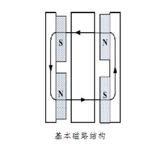
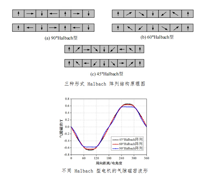
High-grade rare-earth permanent magnets can intrinsically boost air-gap flux density, but premium neodymium-iron-boron materials are prohibitively expensive, limiting their use to niche high-end sectors like aerospace and defense—not viable for mainstream industrial applications. In contrast, the Halbach array reconstructs the air-gap magnetic field distribution by adjusting the magnetization angle between adjacent magnets. This not only enhances effective air-gap flux density but also improves field sinusoidality and suppresses high-order harmonics, thereby refining no-load back-EMF waveforms, reducing torque ripple and electromagnetic vibration, and enhancing operational smoothness.
Commercial Halbach arrays currently feature three magnetization angles: 90°, 60°, and 45°. Smaller angles yield better field sinusoidality and dynamic response but increase assembly complexity and cost. Balancing electromagnetic performance, manufacturability, and cost, the 90° magnetization angle offers the best overall adaptability and has become the standard solution for commercial PCB-based coreless AFPM motors.
V. Pole-Slot Coordination and Core Dimensional Parameter Design
The coreless flat structure lacks physical stator slots, rendering traditional pole-slot matching theories for cored motors inapplicable. To simplify electromagnetic analysis, the industry universally defines each independent closed-loop coil on the PCB substrate as a “virtual slot.” Based on this equivalent model, classical electromagnetic algorithms can be applied to solve no-load back-EMF, perform multi-objective torque optimization, and conduct full-range efficiency validation.
Permanent magnet dimensions are critical determinants of electromagnetic output limits. Electromagnetic simulations show that when the ratio of inner to outer magnet diameter γ = 1/√3, the motor achieves peak electromagnetic power output. In practical engineering, this ratio is typically adjusted to 0.45–0.7 to accommodate varying thermal and spatial constraints. Additionally, magnet thickness is generally set to 1–2 times the effective air gap length to balance material utilization, flux density, and compactness.
VI. Application Prospects and Development Trends of PCB Coreless AFPM Motors
Integrating precision PCB etching, axial-flux flat architecture, and coreless low-loss design, PCB coreless AFPM motors deliver high power density, low torque ripple, lightweight construction, maintenance-free operation, and mass-producibility—precisely matching core requirements of advanced equipment industries. Commercial deployment is already underway across multiple sectors. Supported by a comprehensive specialty PCB portfolio and mature supply chain, Baineng Yunban provides end-to-end support—from conceptual design and prototyping to mass production—accelerating industry adoption and market penetration.
(1) HVAC and Data Center Cooling Systems
In the digital era, data centers are rapidly evolving toward lower PUE values, modular architectures, and higher operational reliability. Traditional centralized cooling systems—with high energy consumption, difficult maintenance, and poor adaptability—are increasingly obsolete, giving way to distributed modular solutions. PCB coreless AFPM motors, with their high efficiency, quiet operation, lightweight ease of installation, and lifetime maintenance-free operation, have become the preferred drive components for cooling fans, air wall modules, and circulation pumps.
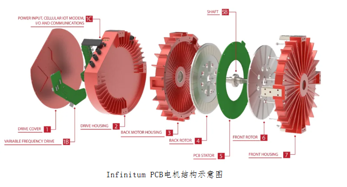
Global leaders like Infinitum and ebm-papst have already achieved large-scale commercialization. Domestically, companies like Pangu Power have pioneered localization efforts; their self-developed PCB350 motor delivers 0.35 kW at 7000 rpm in just 0.5 kg—significantly outperforming traditional cooling motors in weight and efficiency, accelerating domestic substitution. For the demanding 24/7 high-load operation of data centers, Baineng Yunban offers customized 6-layer embedded copper block PCBs and stepped-groove specialty PCBs to enhance local heat dissipation and current capacity, ensuring reliable 7×24 operation of cooling systems.
(2) Joint Actuation for Humanoid Robots
Humanoid robot joints demand actuators that are lightweight, low-inertia, high-torque-density, cogging-torque-free, and cost-effective for mass production.
PCB coreless AFPM motors inherently meet these requirements: zero cogging torque ensures smooth, jitter-free joint motion; flat, lightweight construction reduces redundant inertia and enhances dynamic response; and standardized PCB mass production solves the industry’s pain points of high cost and poor consistency in premium joint motors—positioning it as the core technology for next-generation humanoid joint drives. For ultra-compact joint spaces, Baineng Yunban’s DPC and TFC series ceramic substrates combine ultra-high thermal conductivity with high-precision circuit etching, enabling efficient heat dissipation and electrical interconnection within minimal installation volumes to empower precision joint motors.
Conclusion
Looking ahead, axial-flux permanent magnet motors are continuously evolving toward higher efficiency, ultra-compact thinness, high-precision control, enhanced reliability, and lower mass-production costs. Through PCB precision etching, Halbach magnetic circuit optimization, and innovative winding topologies, PCB coreless AFPM motors have broken free from the structural and performance limitations of traditional motors. In this industrialization journey, specialty PCB manufacturers like Baineng Yunban play a pivotal role in advancing winding carrier technologies. By offering diverse products—including high-multilayer precision boards, high-power thick-copper boards, and ceramic substrates—they provide motor developers with one-stop solutions from electromagnetic design to mass production. With synergistic breakthroughs in rare-earth permanent magnets, novel insulating substrates, and intelligent optimization algorithms, PCB coreless AFPM motors are poised for rapid adoption in humanoid robotics, advanced industrial automation, new-energy thermal management, and precision smart equipment—emerging as a key growth engine for high-quality transformation in the motor industry.
trending news
Contact Us