



Sorry, no sales person is available right now to take your call. Pls leave a message and we will reply to you via email as soon as possible.
Home/ PCB News/ Guide to Collaborative Optimization of FPC Flexible Printed Circuit Board Design and Manufacturing Processes
Guide to Collaborative Optimization of FPC Flexible Printed Circuit Board Design and Manufacturing Processes
2026-05-14
The core logic of FPC (Flexible Printed Circuit) development lies in the deep integration of PCB design and manufacturing process parameters. Every design detail must be supported and implemented by corresponding process capabilities; designs detached from manufacturability are difficult to reliably mass-produce. A high-reliability, mass-producible FPC product with high yield is inevitably the result of collaborative optimization among design, materials, and processes. These three elements are interlinked and mutually reinforcing, forming the fundamental underlying logic for FPC development and successful mass production.
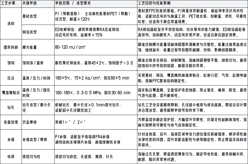
I. Core FPC Manufacturing Processes and Key Parameters
FPC manufacturing belongs to a multi-step, high-precision precision processing system. The process parameters of each core step directly determine the product’s flexibility, electrical stability, bending life, temperature resistance, and structural reliability. The table below systematically outlines the key steps across the entire process, critical parameters, standardized control ranges, and their impact on product performance.
II. Core FPC Design Guidelines (Distinct from Rigid PCBs)
FPC design philosophy fundamentally differs from that of rigid PCBs. During the design phase, engineers must abandon rigid-board habits and prioritize flexibility, bend resistance, structural stability, and manufacturability. Dedicated guidelines must be established for routing in bending zones, overall layout, and structural processes to proactively prevent manufacturing defects and field failures.
2.1 Fundamental Design Rules for Bending Zones
Bend life is a core metric for FPC reliability. Bending zone design must focus on stress relief and structural protection, strictly adhering to standardized bend radius and layout specifications.
(1) Minimum Bend Radius Standards
Static bending (fixed after installation with no repeated movement):
Dynamic bending (continuous repeated flexing during use):
(2) Routing Guidelines for Bending Zones
Routing direction: Traces should preferably run perpendicular to the bend axis to evenly distribute bending stress across all conductors, avoiding localized stress concentration.
Trace geometry: Right angles and sharp corners are prohibited; 45° chamfers or arc transitions must be uniformly adopted to significantly reduce cracking risk.
No-placement zones: Vias, components, and isolated pads are strictly forbidden in bending areas—such features easily create stress weak points, leading to bending fractures or pad detachment.
Basic dimensions: Minimum trace width/space in bending zones is recommended to be ≥0.2mm to ensure conductor structural integrity.
(3) Design Optimizations for High Bend Life
Staggered routing in multilayer boards: Traces in bending zones across different layers should be offset—not vertically stacked—to prevent cumulative stress-induced fatigue fractures.
Mesh copper pour: Replace solid copper pours with mesh patterns in bending zones to maximize board flexibility and minimize stress accumulation while meeting EMI shielding requirements.
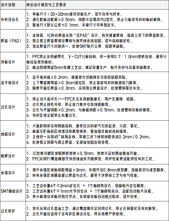
2.2 Comprehensive Standardized Design Guidelines
After completing circuit and structural design, compliant Gerber production files must be generated. Outline geometry, panelization method, pad design, via placement, solder mask openings, stiffener structures, etc., must all align with mass production process standards to ensure high yield and assembly stability.
III. Key Considerations for Design-Process Co-optimization
The key to successful FPC mass production and long-term stable application lies in design adapting to process capabilities and processes supporting design intent. During early-stage design, multiple factors—including material selection, trace precision, structural design, SMT assembly, and cost control—must be holistically considered to fundamentally resolve design-process misalignment.
3.1 Material Selection Matched to Bend Life Requirements
For high-dynamic-flex applications exceeding 100,000 cycles, prioritize 18–25μm PI substrate combined with RA rolled annealed copper foil to maximize fatigue resistance. For static, low-cost scenarios involving only one-time installation without repeated movement, PET substrate with ED electrodeposited copper foil can be used to balance performance and cost. ED copper foil must never be used in dynamic flex applications, as it极易 leads to early trace cracking.
3.2 Trace Precision Aligned with Etching Capability
In standard mass production, 0.2mm/0.2mm trace width/space represents a mature industry process with high yield and stability. Ultra-fine, high-density traces (e.g., 2/2 mil) significantly increase etching difficulty, cost, and defect risk; designers must verify equipment capability and yield levels with the manufacturer early in the design phase. Leading manufacturers can stably mass-produce 2.5/2.5 mil ultra-fine traces with an etch factor >3.0, ensuring precision and yield in high-density applications.
3.3 Via Drilling and Plating: Balancing Difficulty and Cost-Effectiveness
Complex via types such as micro-vias, blind vias, and buried vias impose stringent demands on drilling and plating processes, resulting in higher difficulty and cost. The industry’s optimal balance of cost, reliability, and manufacturability is typically achieved with via inner diameter of 0.3mm and outer diameter of 0.55mm. For high-precision needs, top-tier manufacturers can achieve 0.1mm minimum mechanical drill holes and laser-drilled micro-vias, combined with uniform, dense plating to effectively prevent voids, skip plating, and via fractures.
3.4 Stiffener Design Ensures Assembly and Operational Reliability
Due to the inherent flexibility and low rigidity of FPC substrates, all component soldering areas, connector insertion/extraction force zones, and critical external mating interfaces require FR4, steel, or PI stiffeners. Stiffeners compensate for insufficient rigidity, preventing pad lift, board deformation, and cold solder joints during SMT, assembly, and use.
3.5 Precise Dimensional Tolerance Control
Flexible substrates are prone to dimensional changes due to temperature and humidity, resulting in larger tolerance ranges compared to rigid PCBs. For critical mating or assembly dimensions, tolerance requirements must be clearly communicated to the manufacturer during quoting and process handoff to avoid misalignment or fit issues.
3.6 SMT-Specific Process Controls
Lacking rigid support, FPCs require specialized magnetic fixtures during SMT placement to maintain flatness throughout the process. Additionally, FPCs readily absorb moisture; thus, pre-baking at 80–125°C for 4–8 hours is essential before SMT to fully remove moisture and prevent delamination, blistering, or "popcorning" during reflow.
3.7 Impedance Control Through Collaborative Design
High-speed FPCs require precise stackup, dielectric thickness, and trace geometry to achieve standard characteristic impedances such as 50Ω, 90Ω, or 100Ω. Designers must align impedance strategies with the manufacturer early; leading suppliers can participate in upfront reviews to precisely match layer stackups and trace parameters, tightly controlling process variation to ensure signal integrity and consistency.
3.8 Balancing Performance and Cost
IPC-6013 is the industry benchmark for FPC reliability. Mass production must ensure critical process metrics meet CPK ≥ 1.33 to guarantee consistent batch performance. Under cost constraints, non-critical performance aspects may be adjusted in consultation with the manufacturer, prioritizing core reliability metrics such as bend life, conductivity, and environmental resistance.
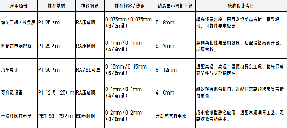
IV. Application-Based Material and Parameter Selection Matrix
End products vary significantly in operating conditions, reliability requirements, and cost budgets, necessitating precise matching of substrate, copper foil, trace parameters, and bend radius to the specific application. Leading FPC manufacturers can comprehensively support consumer electronics, automotive electronics, wearables, medical devices, and more, offering customized solutions that balance thinness, reliability, and cost—from prototyping to high-volume production.
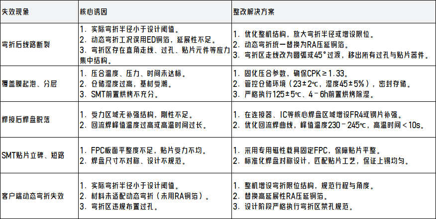
V. Analysis and Solutions for Common Failure Modes
Based on mass production experience and field failure feedback, the table below summarizes frequent FPC failure modes, root causes, and standardized corrective actions. Professional FPC manufacturers leverage end-to-end quality control and production retrospectives to proactively prevent issues like bend fractures, delamination, and pad lift through early design reviews and process optimization.
VI. Conclusion
Successful transition from FPC design to stable mass production hinges on deep understanding of material properties, strict adherence to process guidelines, and unwavering commitment to co-design. Unlike rigid PCBs, FPC design must go beyond mere electrical connectivity—it must embed manufacturability, process stability, bend reliability, and yield considerations throughout the entire workflow, using process constraints to guide design optimization.
Key measures to prevent most FPC failures include application-specific selection of RA copper foil, compliant bend radius design, prohibition of vias in bending zones, controlled coverlay lamination processes, and precise stiffener integration. Grounded in IPC-6013 standards and rigorous control of critical process capabilities, fine-tuned optimization based on actual operating conditions and cost targets enables deep synergy among design, materials, and processes—ensuring smooth transition from prototype validation to volume production and guaranteeing long-term product reliability.
Baineng Yunban strictly complies with IPC-6013 standards, with key processes consistently achieving CPK ≥ 1.33 for mass production. Holding full certifications including UL and ISO9001, we offer one-stop FPC customization services—including design review, process optimization, prototyping, volume manufacturing, and technical support—to accelerate customer R&D and ensure stable, reliable mass delivery.
trending news
Contact Us