



Sorry, no sales person is available right now to take your call. Pls leave a message and we will reply to you via email as soon as possible.
Home/ PCB News/ Core Technology Analysis of Ceramic Pressure Sensors and Detailed Explanation of LTCC Fabrication Process
Core Technology Analysis of Ceramic Pressure Sensors and Detailed Explanation of LTCC Fabrication Process
2026-04-13
In industrial control, aerospace, petrochemicals, and many other fields with extremely high demands for environmental adaptability and measurement accuracy, ceramic pressure sensors are gradually replacing traditional silicon-based sensors to become core sensing components, thanks to their excellent corrosion resistance, high-temperature tolerance, and long-term stability. The fundamental operating principle relies on the deformation-sensing characteristics of ceramic materials: pressure directly acts on the front surface of the ceramic diaphragm, causing a minute elastic deformation, which is precisely captured by the ceramic membrane and converted into a measurable electrical signal, enabling accurate pressure detection.
Currently, the most prevalent type in the market is the thick-film ceramic pressure sensor. Its core design involves printing resistive strain gauges onto the surface of the ceramic diaphragm. When external pressure is applied, the diaphragm undergoes slight deflection, altering the resistance of the strain gauges. This change is then converted by circuitry into a precisely measurable electrical output signal, offering advantages such as high measurement accuracy, fast response speed, and compact structure.
Besides thick-film structures, ceramic capacitive pressure sensors have become a key choice for high-end applications due to their higher sensitivity, lower power consumption, and superior temperature stability. Among these, ceramic capacitive pressure sensors fabricated using Low-Temperature Co-fired Ceramic (LTCC) technology significantly enhance device reliability and miniaturization through integrated monolithic manufacturing processes. Below, we detail the complete fabrication process based on the process flowchart provided by Ampron.
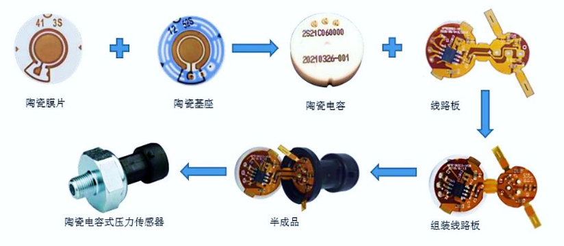
Process Flowchart of Ceramic Capacitive Pressure Sensors
Complete Fabrication Process of LTCC Ceramic Capacitive Pressure Sensors
LTCC (Low-Temperature Co-fired Ceramic) technology is a mainstream approach for passive integration. Its core advantage lies in the ability to co-fire multi-layer ceramic substrates with passive components into a single monolithic structure, enabling high-density integration, miniaturization, and high reliability—making it ideally suited for fabricating ceramic capacitive pressure sensors. The complete process consists of six critical steps, each tightly linked, with precise control of process parameters essential to ensure device performance.
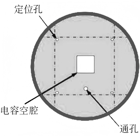
Step 1: Drilling – Laying the Foundation for Multi-Layer Integration
Drilling is the initial step in the LTCC process and is crucial for ensuring subsequent interlayer alignment and reliable interconnection. First, prepared green ceramic tapes are cut into uniformly sized squares. Then, a high-precision punching machine accurately creates three types of critical holes (see figure: Green Tape Drilling Layout): alignment holes, via holes, and capacitor cavities. Alignment holes enable precise stacking and registration of multiple green tape layers, preventing interlayer misalignment that could degrade device performance. Via holes establish conductive pathways between ceramic tape layers, allowing electrical interconnection of interlayer inductors and capacitors. Capacitor cavities provide the spatial foundation for forming capacitors, directly influencing the sensor’s initial capacitance and sensitivity.
Step 2: Silver Paste Filling – Enabling Interlayer Metallic Interconnection
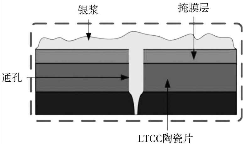
After drilling, the silver paste filling stage begins (see figure: Silver Paste Filling Diagram). Using a dedicated filling machine, high-conductivity silver paste is precisely injected into all via holes. Once cured, this establishes reliable metallic interconnections between passive components like inductors and capacitors across different ceramic layers. The selection of silver paste and filling precision are critical—filling must be complete, bubble-free, and without voids to prevent signal loss or device failure due to poor contact, which is essential for ensuring high-frequency transmission performance.
Step 3: Screen Printing – Forming Passive Components and Circuits
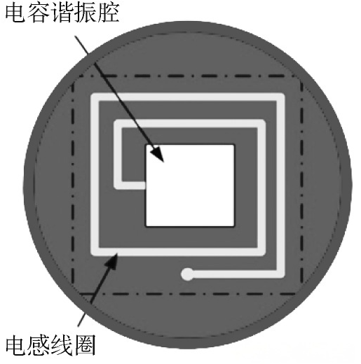
Following silver paste filling, high-precision screen printing is performed (see figure: Screen Printing Diagram). The primary goal is to form passive components such as inductor coils and capacitors, along with associated circuits, directly onto the green tape. According to the pre-designed layout, metal plates (serving as capacitor electrodes) and surrounding spiral metal traces (functioning as planar inductors) are accurately printed onto the green tape surface to ensure circuit pattern fidelity and integrity. After printing, the silver-paste-coated green tapes are placed in an air-circulating oven at 120°C for approximately 5 minutes to remove moisture and organic solvents from the paste, enabling preliminary curing and preparing the tapes for subsequent lamination and co-firing.
Step 4: Lamination – Integrating Multi-Layer Green Tapes into a Monolithic Structure
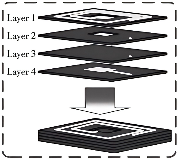
After screen printing and initial thermal treatment, the lamination step commences (see figure: Lamination Diagram). All printed green tapes are stacked in the designed sequence and placed into an isostatic laminator, where they are subjected to a constant pressure of 21 MPa for 15 minutes. This step tightly bonds the multi-layer green tapes into a single, inseparable ceramic substrate with no gaps, ensuring robust interlayer adhesion and preventing delamination or cracking during subsequent co-firing, while also maintaining stable interlayer circuit connectivity.
Step 5: Co-Firing – Solidifying the Ceramic Substrate and Enhancing Structural Stability
After lamination, co-firing solidifies the ceramic substrate—a critical step determining the sensor’s mechanical strength and chemical stability. First, the laminated ceramic substrate is placed in a drying oven at 70°C for approximately 10 minutes to further remove residual moisture and organics. Then, a precision cutter trims the substrate to the required dimensions. Finally, the cut substrates are loaded into a box furnace and fired at a peak temperature of 850°C for 50 minutes, allowing the glassy phase in the ceramic to fully melt and densify the substrate. The entire co-firing cycle lasts about 750 minutes, with precise control over heating, soaking, and cooling rates to ensure high density, dimensional accuracy, and strong bonding between the silver circuits and ceramic matrix.
Step 6: Parallel Seam Sealing – Completing Sensor Fabrication
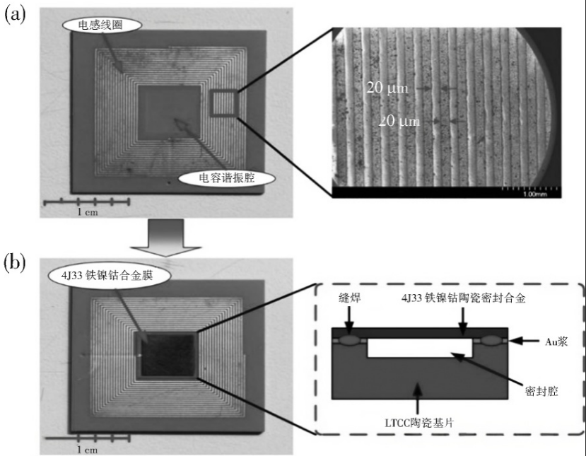
After co-firing, the ceramic substrate forms a complete ceramic structure (as shown in Figure a), but it only integrates passive components and circuits—it is not yet a functional pressure sensor. The capacitor cavity contains only electrode plates and requires the parallel seam sealing step to integrate the sensing diaphragm and complete packaging.
The sensing diaphragm is made from an iron-nickel-cobalt alloy and processed via cold rolling and polishing into a manhole-cover-shaped thin film. This geometry effectively enhances both deformation sensitivity and mechanical strength, ensuring precise response to minute pressure changes. Prior to seam welding, the iron-nickel-cobalt diaphragm undergoes rigorous pre-treatment: surface oxides, contaminants, and oils are thoroughly removed, followed by annealing in a vacuum furnace at 800°C for approximately 40 minutes to relieve internal stresses and improve surface cleanliness and bonding compatibility with the ceramic substrate.
To further enhance sealing reliability, the interface between the ceramic substrate and the alloy diaphragm is gold-plated to reduce contact resistance and strengthen the bond between the metal film and ceramic body. Seam welding is performed in a vacuum environment to minimize oxidation from atmospheric oxygen, preventing degradation of the diaphragm and ceramic substrate while ensuring a hermetic seal that blocks external contaminants (such as moisture and corrosive media) from entering the sensor interior, thereby preserving measurement accuracy and service life.
Upon completion of sealing (as shown in Figure b), the fully integrated LC series resonant circuit on the ceramic substrate enables the final functionality of the ceramic capacitive pressure sensor. When external pressure is applied to the sensing diaphragm, the metal membrane deflects proportionally, changing the distance between the capacitor electrodes and thus altering the capacitance. This capacitance variation is converted into a measurable electrical signal via the LC resonant circuit, ultimately achieving precise pressure detection.
Technical Advantages and Application Value
Ceramic capacitive pressure sensors fabricated using LTCC technology combine the dual advantages of ceramic materials and LTCC processing: ceramics offer exceptional high-temperature resistance, corrosion resistance, and vibration tolerance, enabling operation in extreme environments from -50°C to over 200°C—ideal for harsh applications such as oil extraction and chemical reactors. The LTCC process enables monolithic integration of passive components and the ceramic substrate, significantly reducing device size, enhancing integration density and reliability, while lowering production errors and costs.
Compared to traditional silicon-based pressure sensors, these ceramic capacitive sensors offer higher sensitivity, lower power consumption, wider operating temperature ranges, and superior environmental adaptability. Compared to thick-film ceramic pressure sensors, they achieve higher integration and more compact structures, better meeting the demands of miniaturized, high-precision applications. Today, such sensors are widely deployed in aerospace, oil and gas, chemical processing, and pharmaceutical industries, providing reliable pressure monitoring solutions for extreme environments.
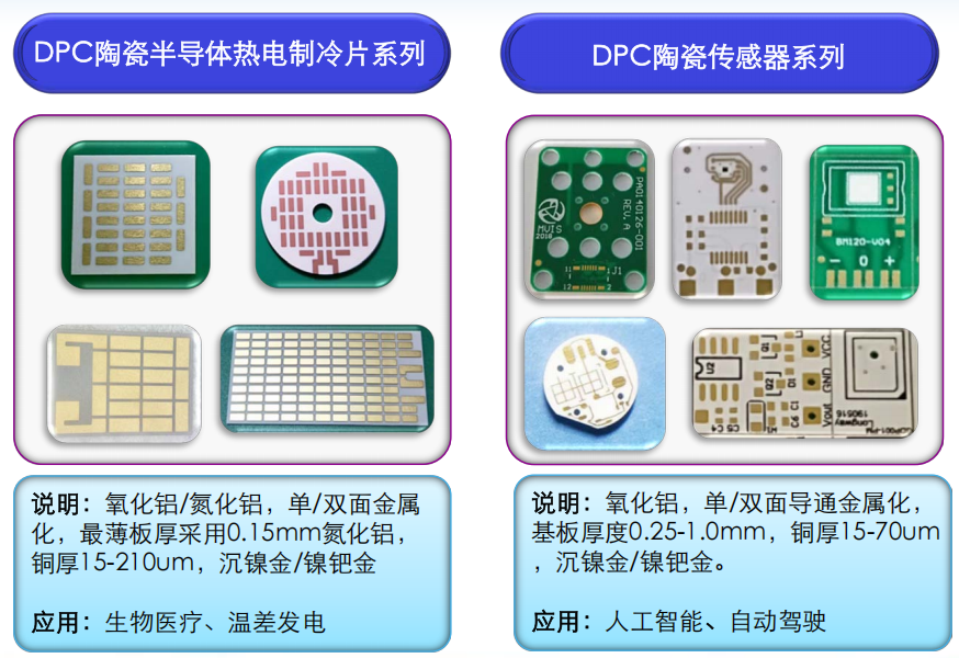
Baineng Yunban Ceramic Substrate Sensor Product Series
Looking ahead, as LTCC process precision continues to improve and material technologies evolve, ceramic capacitive pressure sensors will advance toward higher accuracy, smaller size, and lower power consumption, further expanding their applications in high-end equipment and intelligent sensing systems, and providing core perception capabilities for industrial intelligence upgrades. In this trend, Baineng Yunban has emerged as a key driver of ceramic sensor industry advancement, leveraging its deep expertise in ceramic substrates. Specializing in four core technologies—LTCC, HTCC, DBC, and DPC—and built upon high-purity ceramic materials, Baineng Yunban delivers tailored ceramic sensor solutions through precise parameter optimization and application-specific adaptation. Its products, renowned for outstanding environmental resilience, high accuracy, and reliability, serve critical sectors including automotive electronics, defense, and industrial control, injecting new momentum into the large-scale adoption of ceramic pressure sensors. Capitalizing on its strengths in ceramic substrate manufacturing, Baineng Yunban continuously refines process details to drive ceramic sensors toward greater integration, miniaturization, and high-frequency performance, addressing real-world industry challenges and delivering dependable sensing solutions for the era of ubiquitous connectivity.
trending news
Contact Us