



Sorry, no sales person is available right now to take your call. Pls leave a message and we will reply to you via email as soon as possible.
Home/ Industry News/ 【Application Solution】CAN Bus Communication Circuit Design – VOOHU
【Application Solution】CAN Bus Communication Circuit Design – VOOHU
2026-06-12
CAN communication—Controller Area Network (CAN), proposed by Bosch of Germany in the 1980s, employs a multi-master contention-based protocol, non-destructive bitwise arbitration, and differential signal transmission. These features grant CAN high reliability, real-time performance, and strong noise immunity, making it widely used in automotive electronics and industrial automation.
In automotive applications, the CAN bus connects engine control units (ECUs), TBOXes, body control modules, and more, simplifying wiring harnesses and enhancing vehicle intelligence. In modern robotic systems, the CAN bus is used for joint actuation, sensor fusion, and real-time command transmission—especially suitable for collaborative robots, mobile bases, and humanoid robots that require highly reliable multi-node communication.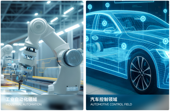
1. CAN Transceiver
The CAN transceiver is an interface IC connecting the MCU to the CAN bus.
1. Key functions include:
Level shifting: Converts single-ended logic signals (TX, RX) from the controller into differential bus signals (CAN_H, CAN_L).
Bus driving: The differential driver uses an open-drain output structure, working with external termination resistors to implement "wired-AND" logic.
Frame processing assistance: Integrated circuits inside the transceiver handle arbitration logic, error detection, bit timing synchronization, etc.
2. Role in CAN communication:
Provides the physical interface between the controller and the bus.
Offers bus fault protection (short-circuit, over-temperature, over-current).
Enhances noise immunity: Differential signaling suppresses common-mode interference. 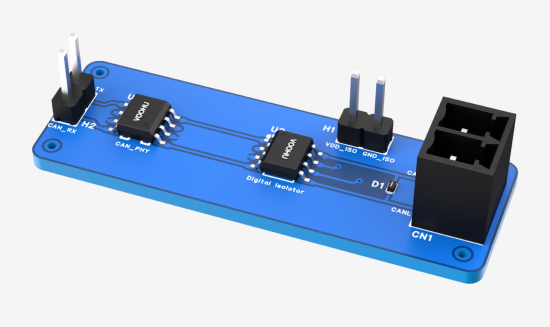
2. Digital Isolator
1. Operating principle
Digital isolators isolate the logic signals (TX, RX) between the CAN transceiver and the controller, breaking ground loops and blocking common-mode noise. Most use capacitive isolation technology, which modulates high-speed signals across an isolation barrier via capacitors—offering low power consumption, small size, and cost advantages.
2. Role in CAN communication
Eliminates ground potential differences between the controller and bus circuitry, preventing switching noise injection.
Improves system reliability: Faults on the isolated side are prevented from damaging the controller MCU.
Enables long-distance communication: Suppresses common-mode voltages exceeding the transceiver’s allowable range.
Currently, most mainstream products integrate the CAN transceiver and digital isolator into a single chip to reduce BOM costs and improve PCB design efficiency.
3. TVS Diode
1. Role in CAN communication
Suppresses electrostatic discharge (ESD) and electrical fast transients (EFT).
Absorbs surge energy caused by load dump or lightning-induced surges in vehicles.
Protects transceiver bus pins from overvoltage damage.
Layout guidelines:
Place the TVS diode as close as possible to the bus connector or transceiver pins, with short and wide traces. Preferably connect it in parallel between CAN_H and CAN_L; secondarily, connect each line to ground.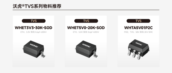
4. Common Mode Choke (CMC)
1. Operating principle
A common mode choke consists of two coils with identical turns wound on the same magnetic core, with opposing winding directions. It presents very low impedance to differential-mode signals but high impedance to common-mode signals, effectively attenuating common-mode currents.
2. Key selection parameters
For CAN bus applications, critical parameters and selection criteria for common mode chokes are as follows:
Typical common mode inductance (Lcm) ranges from 51μH to 100μH @ 100kHz. Higher inductance improves suppression of low-frequency common-mode interference but may increase component size and adversely affect differential signals. Differential-mode impedance should be as low as possible (<10Ω) to prevent CAN signal edge distortion. DC resistance (DCR) must be less than 1Ω; excessive DCR reduces the bus common-mode voltage swing, limiting the number of connectable nodes. Rated current must exceed 200mA and be greater than the bus’s maximum transient or continuous current. Insulation withstand voltage should be ≥1000Vrms to meet system isolation requirements.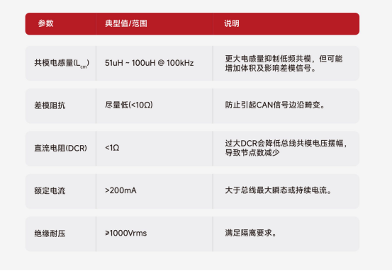
3. Role in CAN communication
Suppresses common-mode radiated interference from external sources (e.g., motors, switching power supplies), improving EMC performance.
Reduces common-mode noise radiated outward via the bus cable acting as an antenna, aiding compliance with electromagnetic interference (EMI) tests.
Works together with termination resistors and TVS diodes to form a complete bus immunity network.
4. Recommended Common Mode Choke Selection for CAN Communication
VOOHU signal-line common mode chokes are optimized specifically for CAN buses, meeting requirements for low DCR, low differential-mode impedance, and high common-mode rejection.
2012 series (e.g., WHLC-2012A-900T0): 90Ω @ 100MHz, 0.35Ω DCR, 300mA—ideal for compact CAN nodes.
3225 series (e.g., WHAC-3225B-110U0): 550Ω @ 100MHz, 0.8Ω DCR, 300mA—suitable for general industrial/automotive CAN nodes.
4532 series (e.g., WHAC-4532A-220U0): 1200Ω @ 100MHz, 1.4Ω DCR, 200mA—designed for high-interference environments near motors or inverters.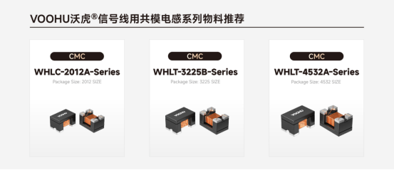
5. Termination Resistor
CAN buses use twisted-pair cables as the transmission medium, with a typical characteristic impedance of 120Ω. When a signal reaches the end of the bus without impedance matching, reflections occur, causing ringing and overshoot that lead to bit errors.
The termination resistor is connected across CAN_H and CAN_L, with a resistance equal to the cable’s characteristic impedance. It absorbs reflected energy and suppresses standing waves, primarily eliminating reflections and providing a DC load path to ensure signal integrity.
6. Complete Circuit Design
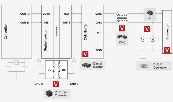
Integrating all the above modules, a typical high-reliability isolated CAN communication circuit is designed as follows:
Layout principles:
- Place the isolator and transceiver as close as possible to minimize digital signal trace length on the secondary side.
- Maintain symmetrical, equal-length differential routing between the transceiver bus pins and the connector, with ~120Ω impedance.
- Primary side (controller side): Power the MCU, primary side of the isolator, and other low-voltage logic directly from the system’s 3.3V or 5V supply.
- Secondary side (bus side): Use a push-pull isolated power supply to generate 5V_ISO, dedicated to powering the transceiver VCC and the secondary side of the isolator.
- Ground planes: Keep primary GND and secondary GND_ISO completely isolated. Connect them to chassis ground (or protective earth PE) via a 1MΩ resistor in parallel with a 10nF high-voltage capacitor to dissipate static charge and provide a high-frequency noise path, preventing floating potential buildup.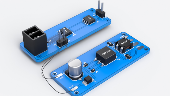
Frequently Asked Questions
Q1: Why does the CAN bus need termination resistors? How should their value be selected?
A1: Termination resistors match the cable’s characteristic impedance to absorb signal reflections and prevent ringing and overshoot. Standard CAN buses use twisted-pair cables with a characteristic impedance of 120Ω, so 120Ω resistors should be used, connected across CAN_H and CAN_L. Typically, one 120Ω resistor is placed at each end of the bus.
Q2: What role does the common mode choke play in a CAN bus? What parameters should be considered during selection?
A2: The common mode choke suppresses external common-mode interference (e.g., from motors or switching power supplies) and reduces common-mode radiation from the bus cable, helping pass EMC tests. Key selection parameters include: common mode inductance (51μH–100μH @ 100kHz), differential-mode impedance (<10Ω), DC resistance (<1Ω), rated current (>200mA), and insulation withstand voltage (≥1000Vrms). VOOHU offers 2012/3225/4532 series signal-line common mode chokes that meet these requirements.
Q3: How should the CAN bus protection circuit be designed? Where should the TVS diode be placed?
A3: The protection circuit must suppress ESD, EFT, and load-dump surges. The TVS diode should first be connected in parallel between CAN_H and CAN_L, and secondarily from each line to ground. In layout, place it as close as possible to the bus connector or transceiver pins, with short and thick traces.
Q4: Why use a digital isolator in an isolated CAN circuit? How should the isolated power supply be designed?
A4: The digital isolator breaks ground loops and blocks common-mode noise between the controller and bus, preventing faults on the isolated side from damaging the controller MCU. The isolated power supply can use a push-pull isolation transformer to generate 5V_ISO, dedicated to powering the transceiver VCC and the isolator’s secondary side. VOOHU provides push-pull transformers such as WHST06D02A0, which work with isolators to form a complete isolation solution.
Q5: How to co-select CAN transceivers, isolators, and common mode chokes?
A5: First, select a CAN transceiver (e.g., SIT1042, SIT1051) based on data rate and number of nodes. If isolation is required, choose either an integrated isolated transceiver or a discrete “isolator + transceiver” solution. Place a common mode choke (VOOHU 3225 or 4532 series) near the connector at the bus interface to filter common-mode interference, and add a TVS diode in parallel for surge protection. Also include a 120Ω termination resistor. VOOHU offers a complete CAN interface component kit—including common mode chokes, TVS diodes, push-pull transformers, and connectors—and supports reference circuit design.
From its founding in 2018 to global expansion by 2026, VOOHU Electronics has become a trusted partner for over 1,000 enterprises through “superior quality, competitive pricing, attentive service, and reliable delivery.” If you’re also looking for a communication components supplier that saves you “time, money, and hassle,” give VOOHU a try—after all, the choice of 100+ listed companies can’t be wrong.
Choose VOOHU – Truly Reliable. More than just a slogan—it’s the answer written by over 1,000 customers through nine years of trust.
trending news
Contact Us