



Sorry, no sales person is available right now to take your call. Pls leave a message and we will reply to you via email as soon as possible.
Home/ Industry News/ Why does the BMS need to have a separate RTC module?
Why does the BMS need to have a separate RTC module?
2026-04-25
I. What is a BMS?
BMS stands for Battery Management System, a device designed to monitor the status of energy storage batteries. Typically, a BMS appears as a circuit board or a hardware module.
1. Real-time Monitoring
Voltage Monitoring: Detects the total voltage and the voltage of each cell or module;
Current Detection: Measures the total charging and discharging current;
Temperature Monitoring: Uses temperature sensors placed throughout the battery pack to detect temperature changes at various points;
2. State Estimation
SOC (State of Charge): Estimates remaining capacity using coulomb counting and open-circuit voltage methods.
SOH (State of Health): Estimates battery health by analyzing internal resistance growth, full-charge capacity degradation, charge/discharge cycle count, etc., reflecting the degree of battery aging.
SOP (State of Power): Estimates the maximum discharge power the battery can deliver and the maximum charge power it can accept over a short period (e.g., several seconds to tens of seconds).
SOE (State of Energy): Estimates the remaining usable energy (in kWh), providing a more direct basis for predicting driving range.
3. Protection & Safety Management
When abnormal or hazardous conditions are detected, the BMS immediately takes action to cut off power.
Overvoltage Protection: Cuts off the charging circuit if any cell voltage exceeds the safe upper limit, preventing overcharging.
Undervoltage Protection: Cuts off the discharging circuit if any cell voltage drops below the safe lower limit, preventing over-discharging.
Overcurrent Protection: Disconnects the circuit if charging or discharging current becomes excessive, preventing short circuits or overloads.
Overtemperature Protection: Reduces power output or disconnects the circuit if battery temperature exceeds the safety threshold.
Short-Circuit Protection: Instantly disconnects the circuit (within microseconds) in case of a severe short circuit.
Insulation Monitoring: Monitors the resistance between the high-voltage system and the vehicle chassis to prevent leakage risks.
Fault Diagnosis & Logging: The BMS records all fault information and generates diagnostic trouble codes (DTCs) to support subsequent maintenance.
4. Controls balancing circuits to maintain consistent charge levels across all cells, extending battery life;
5. Timestamps critical events and stores them in flash memory for fault tracing and warranty analysis.
II. Why Integrate an RTC into a BMS? — Taking the YSN8563MS as an Example
The core purpose of integrating an RTC (Real-Time Clock chip, such as the common YSN8563) into a BMS is simple: to provide the system with an absolute, traceable, and ultra-low-power "time reference" even during "power-off + sleep" states.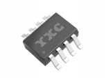
YSN8563MS Product Image
(1) Sleep Timer Wake-up – Turning "Always-On Standby" into "Intermittent Health Checks"
After the vehicle is turned off and the main MCU powers down, the RTC continues running on a coin-cell battery with a current draw of only 0.3–0.5 µA. At preset intervals (e.g., every 4 hours or daily at 2 a.m.), it outputs an interrupt signal to wake the BMS from Deep-Sleep mode to perform voltage and temperature inspections of the cells.
(2) Static SOC Correction
Coulomb counting tends to drift over time and must be corrected using the open-circuit voltage method. This method requires the battery to remain idle for ≥2 hours, and the system must know the exact "true idle duration." The RTC keeps continuous time tracking; upon system restart, it compares the current time with the last shutdown timestamp to calculate the actual idle duration. If this duration is ≥2 hours, the open-circuit voltage method is triggered. After completion, the system returns to sleep—saving power while ensuring no inspection is missed.
(3) Precise Fault Timing
National standard GB38031-2020 and accident investigations require key events to carry timestamps with 1-second accuracy. The RTC continues keeping time even during system power loss, providing absolute calendar timestamps for DTCs, overcharge/overdischarge events, thermal runaway logs, and EDR crash records—avoiding evidence invalidation due to "sequence numbers without precise timing."
Timestamped Temperature Sampling: Calendar-based aging (both high-temperature and cycle-induced) is closely tied to temperature and time. The RTC enables precise timestamping of temperature samples, allowing the BMS to accumulate high-temperature exposure duration, track cycle counts and intervals, dynamically adjust maximum charging current, and issue early SOH degradation warnings—enhancing warranty reliability.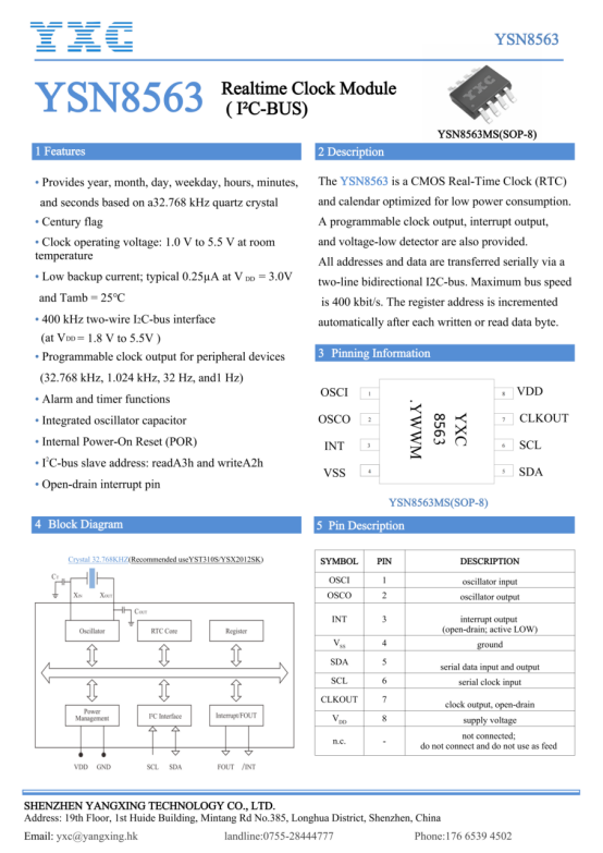
YSN8563MS Datasheet
III. Why Use a Dedicated RTC Instead of the MCU’s Built-in RTC?
Higher Accuracy: Dedicated RTC chips (e.g., the 8563) typically use an external 32.768 kHz crystal oscillator, offering significantly better time accuracy than most MCU-integrated RTCs.
Lower Power Consumption: In sleep mode, dedicated RTCs can achieve microamp or even nanoamp-level power consumption—much lower than the overall sleep power of an MCU—enabling long-term BMS sleep operation.
Greater Reliability: As an independent chip, it remains unaffected by MCU program crashes or resets. Even after a vehicle system reboot, time data is preserved (thanks to a backup battery or super capacitor).
Integrated Features: RTC chips like the YSN8563 integrate timers, alarms, clock outputs, and precise timestamping functions, simplifying system design and enabling accurate fault localization.
trending news
Contact Us